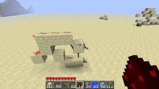
Video: RAM and D FLIP FLOPS made simple. by Steve
How to build it
- Build the T-Shaped Frame
Start a single D flip-flop cell by placing a row of 4 solid blocks. Add 1 block to the side to form a T-shape, plus 1 block connecting this unit to the neighbor cell along the shared write line.
- Place the Redstone Dust
Place 5 pieces of redstone dust on the frame and ground as shown in the layout: along the write line connection, on the top blocks of the T-frame, and in the lower RS NOR latch gap.
- Add the Three Repeaters
Place 3 redstone repeaters for the cell: one leading from your data input into the cell, one along the shared write line to carry the signal to the next cell in tandem, and one inside the latch pathway.
- Attach the Four Redstone Torches
Mount 4 redstone torches onto the sides of the blocks: one at the input gate block, two facing each other in the lower section to form the RS NOR latch core, and one on the back for the output.
- Tile Additional Cells for Multi-Bit RAM
Repeat the exact same T-shaped structure side-by-side (for example, 4 cells for 4-bit RAM) so that the shared write line connects across all of them while keeping each data input separate.
- Connect the Input & Output Buses
Run parallel lines of blocks and redstone dust (a bus) from your input levers into the front of each D flip-flop, and run output lines from the back of each cell. Add an inverting torch at the end of each output line if you want active-high (non-inverted) readings.
How it works
This RAM module is built around a classic torch-and-repeater D Flip-Flop (technically a gated D latch) designed by BennysCube, combined with parallel input and output buses:
- The Write Gate: In its default state, the shared Write line keeps the back blocking torches powered on. While these torches are on, changing the front data inputs has no effect on the stored memory.
- Writing Data: When you toggle the Write lever, the blocking line turns off. Now the current state of each input bit (
1for on,0for off) is allowed through into the cell. - RS NOR Latch Storage: At the bottom of each cell, two redstone torches and three redstone dust form an RS NOR latch with an integrated reset torch. If the data input is
1while Write is active, the latch flips to the set state; if the data input is0while Write is active, the reset torch forces the latch back to zero. - Locking the Memory: Once you turn the Write lever back to its default locked state, the stored bits remain frozen in the latches until the Write line is activated again.
Tips & variations
- Watch the Active Write Window: Because this circuit acts as a level-triggered D latch, any changes made to the input levers while the Write lever is active will immediately alter the stored value. Set your binary input first, then pulse or toggle the Write line.
- Fixing Inverted Outputs: If all inputs are
0000and the raw latch outputs read1111, simply place a redstone torch at the end of each output line (or right behind each cell) to invert the signal back to true binary. - Expanding Capacity: Add more cells in tandem along the same Write line to increase bit width (e.g., from 4-bit to 8-bit). To store multiple separate bytes of RAM, build another row of cells further down the same input data bus with its own separate Write line.
- Bus Cutoffs: You can place sticky pistons with solid blocks over the output lines to cut off or enable specific RAM banks from feeding onto a shared output bus.