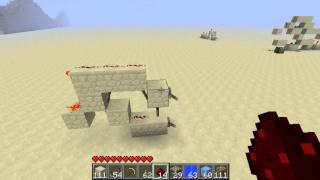
Video: Minecraft Redstone Tutorial: RFB Ep.8 D Flip-Flops & Gated D Latches by V3Slayer
How to build it
- Set Up the Data and Clock Inputs
Place two levers on solid blocks to act as your Data (D) input and your Clock/Enable (C) input. Leave space behind them to run separate redstone dust lines into your logic gates.
- Build the Input Gating Stage (Design A - Gated D Latch)
Run the Data line and the Clock line toward a redstone torch inverter setup. When the Clock line is powered ON, it should hold the gating torches in a locked state so toggling the Data lever does nothing to the output.
- Create the Memory Loop
Behind the input gate, construct a feedback loop using solid blocks, redstone torches, and redstone dust (an RS NOR-style latch). Connect your output indicator, such as a piston, to the end of this memory loop.
- Add Optional R and S Override Inputs
If you need to force the memory state regardless of the clock, place asynchronous Reset (R) and Set (S) levers directly feeding into the two sides of the memory loop.
- Add an Edge Trigger for a D Flip-Flop (Design B)
To convert the level-triggered latch into a true positive-edge D Flip-Flop, wire a pulse/edge trigger onto the Clock input line. Now the output will only update to match the Data lever at the exact moment the Clock switches from OFF to ON.
- Build the 1-Wide Vertical Variant (Design C)
For compact systems, build the circuit vertically in a 1-block-wide footprint by stacking blocks, torches, and repeaters in a single column. Wire the non-inverted clock line to a bottom torch that locks or unlocks the upper data path.
- Synchronize Delayed Designs with Repeaters
When building compact repeater-based variants, place a redstone repeater set to a 1-tick delay to match the delay of a redstone torch. This synchronizes the signals switching between the live Data input and the internal holding loop.
How it works
Both circuits control when a Data input (D) is allowed to pass through to the Output (Q) using a Clock or Enable input (C):
- Gated D Latch (Level-Triggered): The clock acts as a gate. In a low-level trigger design (Design A), while the clock is OFF, changes to the
Dlever pass directly through to the output piston. Turning the clock ON powers the blocking path and locks the current state into the feedback torch loop, ignoring any further changes toD. (In non-inverted designs like Design C, the output updates while the clock is ON and locks when the clock turns OFF.) - D Flip-Flop (Edge-Triggered): By adding an edge trigger to the clock line (Design B), the gate only opens for a brief pulse when the clock transitions from OFF to ON (positive edge). The circuit samples
Dat that instant, updates the output, and immediately locks again even if the clock stays ON. - Asynchronous Overrides: The optional
RandSinputs bypass the clock gate entirely to force the latch into an ON or OFF state.
Tips & variations
- Shift Registers & RAM: Use the 1-block-wide vertical design (Design C) when building 16-bit registers or redstone computers. You can line multiple slices up side-by-side and feed the output of one into the
Dinput of the next so data shifts across on every clock pulse. - Repeater Timing Mistake: In synchronized loop designs, keep the synchronizing repeater at 1 tick so it matches the 1-tick delay of a redstone torch. Increasing the delay will desynchronize the loop and cause data corruption or rapid piston oscillation.
- High vs. Low Trigger Variant: You can invert the trigger level of the compact latch simply by swapping the input dust/repeater configuration for a redstone torch on the clock line.