Video: Redstone Displays - LRR #9 by mattbatwings
How to build it
- Build the 2x2 Pixel Display Grid
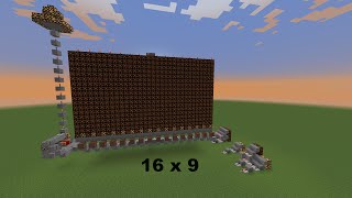
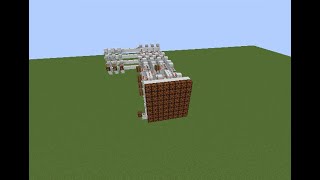
Create a flat wall of redstone lamps grouped into 2x2 squares (4 lamps per pixel). Behind each 2x2 pixel, build a stackable powering module with a single redstone dust input so that powering that dust lights up all four lamps of the pixel, then tile it into an 8x8 grid (64 modules total).
- Add a Target Block Image ROM (Optional)
To store pre-made images at the same height as the screen, run horizontal pixel lines straight back from each pixel and build vertical blue glass towers behind them for each stored image. Replace glass blocks with Target blocks only at the pixel positions you want lit, then power a tower from the bottom with a lever to redirect the signal into those pixels.
- Construct the XY Matrix Decoder
To plot individual coordinates (with 0,0 at the bottom-left), build an X decoder along the columns using vertical glass towers and a Y decoder along the rows using horizontal redstone lines. Place a grid of redstone torches where every torch is held off by both its row line and its column tower; when an X and Y value are selected, both lines unpower at that intersection and only that single torch turns on.
- Attach SR Latches for Multi-Pixel Plotting
Insert an SR latch between each matrix decoder output and its pixel input so plotted pixels stay lit. Wire all the latch reset lines together to a single Clear button at the front, and add a Plot button gate to the decoder so the 0,0 pixel does not automatically lock on while idle.
- Upgrade to Data Latches (Repeater Locks)
For full read/write control, replace the SR latches with repeater-lock data latches kept locked by default via comparators. Connect the back of every locking repeater together using vertical glass towers tied to a single Data lever (0 or 1); when the matrix decoder pulses a coordinate, that pixel's repeater briefly unlocks and grabs the current data state.
- Wire the Plot-All / Screen Reset Override
Add comparator overrides to the Y row lines and a cutoff line to the X column lines of your matrix decoder so a 'Plot All' button forces every decoder row and column off at the same time. Pressing Plot All turns on every decoder torch simultaneously, unlocking all pixel repeaters so they all grab a 0 (clear screen) or 1 (fill screen) from the Data lever.
- Build a Frame Buffer for Animations
Place an SR latch stage followed directly by a D-latch (repeater lock) stage behind each pixel. Use a single vertical glass tower per column with two dust lines: when you press the push-frame button, the left dust flashes the D-latches to capture the finished drawing onto the screen while the right dust simultaneously resets the SR latches for the next frame.
- Add Comparator Passthrough for Multiple Inputs
To plot multiple XY coordinates at the same time, rebuild the matrix decoder using a comparator at each pixel intersection that is canceled from both sides by a row repeater and a column glass tower. Feed outputs from a second matrix decoder behind it through a comparator into the block behind each pixel's dust at signal strength 1—strong enough to power the pixel output, but too weak to travel down the Y decoder line and interfere with other repeaters.
How it works
These display systems work by combining modular pixel addressing with sequential memory:
- 2x2 Pixel Density: A 1x1 lamp grid is difficult to wire without crosstalk and lag. Grouping 4 lamps into a 2x2 pixel gives enough space behind the wall for clean, tileable input lines.
- Target Block ROM: Vertical glass wire towers run past the horizontal pixel inputs without connecting. Placing a
Targetblock at a specific intersection redirects the redstone dust on the glass tower into that pixel's line when the tower is powered. - Matrix Decoding (NOR Logic): Each pixel intersection has a redstone torch powered by two sources: its X column and its Y row. Because both inputs must turn off for the torch to turn on, it acts as a logical NOR gate that isolates a single (X, Y) coordinate.
- Double Buffering: Drawing complex frames pixel-by-pixel directly on the screen looks slow. By drawing into hidden SR latches first and then pulsing a layer of D-latches (locked repeaters), the entire frame transfers to the lamps at once while the SR latches clear themselves for the next frame.
- Signal-Strength Passthrough: By restricting an incoming signal from a rear decoder to signal strength 1 via a comparator, the signal passes through a solid block into the output pixel line without reaching the adjacent row repeaters on the Y decoder bus.
Tips & variations
- Faster Animations with Trapdoors: Redstone lamps take 2 redstone ticks (4 game ticks) to turn off. For fast animations, replace the lamps with trapdoors (and optionally use a clean resource pack) so pixels respond instantly.
- Extending Past 8x8 Screens: Vertical glass towers run out of signal strength after 8 pixels. To extend a tower upward, use either a backward-facing repeater into a solid block or a two-torch inverter tower into a solid block.
- Keep Extended Towers Synchronized: Extending a glass tower adds delay to the upper pixels (1 redstone tick for the repeater method, 2 ticks for the two-torch method). Add matching 1-tick or 2-tick repeater delays to the bottom 8 pixel lines so the entire column updates on the exact same tick.
- Common Mistake: When extending a glass tower with a repeater or torch, always remember to swap the glass block at the extension point for a solid block, or the repeater/torch won't power the rest of the tower.