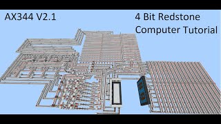
Video: Minecraft Bedrock ALU Tutorial - Redstone Computing by TheDarkness344
How to build it
- Set Up the 4-Bit Input Bus
Build four parallel input lines spaced apart for the 1, 2, 4, and 8 binary bit values, placing the least significant bit (1) on the left and the most significant bit (8) on the right. Place a lever at the start of each line to act as your manual data input.
- Place Slab Diodes for Registers
At the end of each input line, step the redstone signal up using a top slab rather than a repeater or glass block. In Bedrock Edition, slabs act as zero-tick one-way diodes that allow signals to travel upward while preventing register feedback from flowing backward into the input bus.
- Frame the A and B Register Flip-Flops
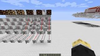
Branch each bit line into two parallel paths so every bit has a Location A and a Location B. Place 1-tick repeaters leading into the two paths and build elevated block frames above them to house the D flip-flop memory latches.
- Install the D Flip-Flop Torch Latches
Attach redstone torches to the register blocks to create the vertical feedback loops for the D flip-flops. Place redstone dust connecting the upper torch outputs to the lower torch blocks, then remove any temporary supporting blocks in the center so each bit stores its state cleanly.
- Wire the Register Write Control Lines
Run two horizontal control buses across the top of all four bit slices—one for Register A and one for Register B. Place inverting redstone torches over the corresponding A and B latches (alternating A, B, A, B across the array) and add repeaters behind the torches if the signal strength runs out.
- Build the Input Inverter Modules
Extend the output torches from both A and B registers forward into dedicated inverter circuits. For each line, place a lower 1-tick repeater path and an upper redstone torch path so the signal can travel through either an uninverted or inverted route.
- Add Pistons to Control Input Inversion
Mount downward-facing sticky pistons above the inverter blocks for both Register A and Register B, and wire them to two separate horizontal control lines (Invert A and Invert B). Toggling these lines pushes a block into place to switch between the normal signal and the inverted signal.
- Construct the Logic and Ripple-Carry Adder Stages
Route the outputs of the A and B inverters into the main logic and ripple-carry adder section. Build the XOR and AND logic gates for each bit slice, linking the carry-out of each bit from left to right (from the 1s bit toward the 8s bit) and adding a Carry In input on the least significant bit.
- Wire the Carry Cut and Adder Bypass Lines
Run control lines across the adder array for AND enable, Cut Carry, and Cut Adders (Bypass Adders), using Bedrock glass mechanics where needed to prevent accidental piston powering. Finish the output stage by adding an Invert Output control line and an ALU Out read gate.
How it works
This ALU processes data in three distinct stages: temporary storage, input manipulation, and arithmetic/logic execution.
- Dual D Flip-Flop Registers: A single 4-bit input bus feeds both Register A and Register B. Because slabs act as one-way diodes, both registers can sit on the same input lines without back-feeding each other. Pulsing the Register A or Register B control line unlocks only those specific latches to store the first and second numbers on consecutive clock cycles.
- Independent Input Inverters: Each register output passes through a piston-controlled inverter. By enabling
Invert AorInvert Balong withCarry In, the ALU performs subtraction using two's complement arithmetic (eitherA - BorB - A). - Control Flags & Opcodes: By combining control lines, the same hardware performs multiple bitwise and arithmetic functions:
- SUM (001):
ALU Out - A - B (010):
ALU Out+Invert B+Carry In - B - A (011):
ALU Out+Invert A+Carry In - AND (100):
ALU Out+AND+Cut Carry+Bypass Adders - XOR (101):
ALU Out+Cut Carry - OR (110):
ALU Out+AND+Cut Carry - NOR (111):
ALU Out+AND+Cut Carry+Invert Output
- SUM (001):
Tips & variations
- Use Slabs, Not Glass, for Diodes: In Minecraft Bedrock Edition, redstone signals can travel both up and down on glass blocks, whereas top slabs only allow signals to travel upward. Using glass at the register input will cause the D flip-flop feedback loop to leak back into your input bus.
- Repeater Placement on Control Lines: When extending the Register A and B control lines across wider bit widths (such as 8-bit or 16-bit), never place a repeater directly on top of a block holding a control torch. Place the repeater on the block behind the torch block so it properly powers the block and turns the torch off.
- Clean Up Temporary Blocks: Always remove scaffolding blocks inside the D flip-flops and inverters as you build each slice; stray solid blocks can accidentally cut redstone lines or redirect torches in tightly packed slices.
- Reversing Bit Order: This build places the Least Significant Bit (1) on the left and the Most Significant Bit (8) on the right. If you prefer the 1s bit on the right, reverse the direction of the half-adder connections and route the carry line from right to left.