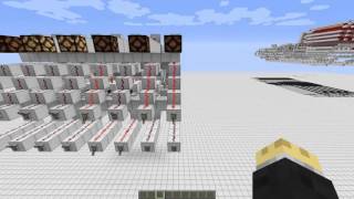
Video: The Arithmetic Logic Unit - Let's Make a Redstone Computer! #2 by mattbatwings
How to build it
- Build the 8-Bit Carry Cancel Adder Base
Construct an 8-bit vertical Carry Cancel Adder (CCA) with eight vertically stacked bit slices. Each slice needs an initial XOR gate for the A and B inputs, a vertical comparator carry tower, and a second XOR gate that combines the first XOR result with the carry signal.
- Add Invert A and Invert B Control Lines
In front of the A and B input lines, build selectable inverters (XOR gates controlled by a vertical control line). Wiring a lever to the Invert A line and another to the Invert B line lets you flip all 8 bits of either input on demand.
- Wire the Carry-In (Cin) Input
At the very bottom of the CCA's vertical comparator carry tower, place a power input controlled by a lever. Turning on Carry-In together with Invert B converts the adder into a two's complement subtractor (computing A minus B).
- Install the Flood Carry Tower
Build a vertical tower of repeaters running alongside all 8 bits that feeds directly into the carry input of the final XOR gates. When this Flood Carry control line is powered, it forces the carry bit of every slice to 1, preventing carries from propagating between bits and inverting the final XOR stage.
- Add the XOR-to-OR Override Line
On the first XOR gate of each slice, tap the internal redstone dust line that represents the OR of A and B and route it toward the first stage output through a comparator. Connect all eight comparators to a vertical control tower so that un-canceling them overrides the XOR output with A OR B and disables carry generation.
- Attach the Right-Shift Output Stage
At the output of the ALU, split each bit line into two paths: one straight through for the regular output, and one routed down by one bit position for a right-shifted output. Use a control line with cancelling comparators or repeaters to select between the normal output and the right-shifted output.
- Build the Control ROM (Optional)
To avoid toggling the control lines manually, run opcode selection lines perpendicular to the six control inputs (Invert A, Invert B, Carry-In, Flood Carry, XOR-to-OR, and Right Shift). Place redstone torches at the intersections matching each operation's truth table so selecting one function automatically powers the required controls.
How it works
Rather than duplicating inputs across eight separate logic circuits, this ALU manipulates the boolean algebra inside a single full-adder array using five core control signals plus an output shifter:
- Addition & Subtraction: A standard full adder outputs
Sum = A XOR B XOR C. With all control signals off (0), the CCA adds A and B. Enabling Invert B and Carry-In (Cin) computesA + !B + 1, which is two's complement subtraction (A - B). - XOR & XNOR (Flood Carry): Bitwise logic requires isolating each bit so carries do not ripple across slices. Turning on Flood Carry forces every slice's
Cinput to1. SinceX XOR 1 = !X, the sum equation simplifies to!(A XOR B), giving bitwise XNOR. Also turning on Invert B flips the output back to bitwise XOR. - OR, NOR, AND & NAND (XOR-to-OR): Enabling the XOR-to-OR line overrides the first XOR gate with an OR gate and disables carry generation so all internal carries stay
0(unless Flood Carry is on). By De Morgan's laws, combining an OR base with input/output inversions produces the remaining gates:- OR:
XOR-to-ORonly. - NOR:
XOR-to-OR+Flood Carry(inverts output). - NAND:
XOR-to-OR+Invert A+Invert B(inverts inputs). - AND:
XOR-to-OR+Invert A+Invert B+Flood Carry(inverts inputs and output).
- OR:
- Bit Shifting: Left shifting (multiplying by 2) requires no extra hardware—simply feed the same number into both A and B and run ADD (
X + X = 2X). Right shifting (dividing by 2) is handled by the output multiplexer, which drops the least significant bit and shifts every other bit down one position.
Tips & variations
- Bonus Implies Operations: Because Invert A and Invert B are controlled independently, turning on
XOR-to-OR+Invert Agives Implies (!A OR B), and addingFlood Carrygives Nimplies. - Beginner Mux Alternative: If modifying a CCA feels too complex, you can build a simpler (though much larger) ALU by wiring inputs A and B in parallel to separate Adder, Subtractor, OR, AND, XOR, NOR, NAND, and XNOR modules, then using comparator cancellation towers on the outputs to allow only one result through at a time.
- Signal Timing: When using a Carry Cancel Adder, wait for the vertical comparator carry tower and control towers to fully propagate before latching the ALU output into a register.