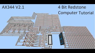
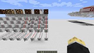
Video: How to Build a Redstone Computer Part 2: The ALU by Melneusc
How to build it
- Elevate the Starting Platform
Start your build roughly 7 blocks above the ground. Giving yourself vertical clearance makes it much easier to route the lower logic paths and connect future computer components.
- Build the First Input XOR Gate
For your first bit (value 1), place two input levers leading into an inverted XOR gate using building blocks, redstone torches, and redstone dust. This gate compares your two raw binary inputs so that it outputs a signal only when a single input is active.
- Construct the Secondary Logic Stage
Behind the first gate, build a second XOR gate in line with the output. This second stage acts as a double-checker that compares the result of the first gate against any incoming carry signals from previous bits.
- Tile the Design for Four Bits
Replicate this dual-gate module side-by-side four times to represent your four binary bits (1, 2, 4, and 8). Keep a small gap between each module so the wiring stays separated and easy to trace.
- Wire the Upper Carry Line
Above the primary logic level, build the carry-in bridge connecting each bit to the next higher bit. Tap a line from the input comparison of each bit and route it up and over into the secondary stage of the adjacent bit.
- Add the 16-Bit Overflow Line
On the final fourth bit (value 8), extend the carry-out line one step further to create a dedicated overflow output. This line triggers a value of 16 when both 8-bit inputs (or an 8-bit sum plus a carry) are active.
- Place Output Displays and Labels
Attach redstone lamps to the final outputs of all four bits and the 16-bit overflow line. Place signs on the inputs and outputs to label the binary values (1, 2, 4, 8, and 16) for easy testing.
How it works
This 4-bit ALU operates as a ripple-carry binary adder broken into two distinct calculation stages per bit:
- Stage 1 (Raw Input Comparison): Each bit starts with an XOR gate comparing Input A and Input B. If only one lever is pulled, the signal passes straight through to represent a basic sum. If both levers are off—or both are on—the XOR output turns off.
- Carry Detection: When both inputs on the same bit are turned on (for example,
1 + 1on the first bit), that single column cannot display a value of 2. The circuit detects this overflow condition and sends a signal up to the elevated carry line. - Stage 2 (Carry Integration): The elevated carry line travels sideways into the second logic gate of the next bit over (the 2s place, 4s place, or 8s place). This secondary stage compares the new bit's raw total with the incoming carry signal, cascading the math down the line up to a maximum overflow bit of 16.
Tips & variations
- Color-Code Your Wiring: Use different colored wool or concrete for the first XOR gate, the second XOR gate, and the upper carry line so you can visually debug where signals travel.
- Signal Delay: Because the carry line ripples sequentially from the 1-bit up to the 16-bit overflow, give the redstone torches a moment to settle before reading the final lamp output.
- Expanding the ALU: Because the 4-bit architecture simply tiles 1-bit modules connected by a carry line, you can expand it to 8 bits by adding four more identical slices.