
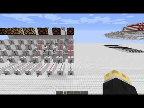
Video: Compact Redstone ALU + Tutorial by n00b_asaurus
How to build it
- Build the Base Binary Adder Slice
Start by constructing a single slice of Ammorth's compact 2-block-wide full binary adder. It is easiest to build and modify one single-bit slice completely before cloning or stacking it horizontally to your desired bit width.
- Tap the SUM Output Tower
At the front output of the full adder, build a vertical torch pillar (block, torch on top, block on top of that, and another torch) to carry the SUM signal upward. Place a block and repeater feeding into the top of this pillar, and run a 2-block-wide horizontal line of blocks with redstone dust across it to act as the SUM enable control line.
- Tap the XOR Output Tower
Locate the internal inverted XOR torch inside the middle of the adder slice and place a block directly above it to start a second vertical torch tower. Add an upside-down slab next to the top torch with a repeater running into it, topped by a 2-block horizontal redstone dust line for the XOR enable control.
- Tap the AND Output Tower
Find the internal AND gate torches inside the adder and build a third vertical torch pillar above them, using a side-mounted torch and block to keep the signal properly inverted. Add a block with a repeater feeding into this top torch, using an upside-down slab and redstone dust for the horizontal AND enable line so you don't accidentally cut off the torch below.
- Bridge the Master Output Bus
Connect the outputs of all three vertical control towers (SUM, XOR, and AND) per slice by bridging solid blocks across the top from back to front. Run a continuous strip of redstone dust along the top of this bridge to form the bit's main output line, then tile the completed Phase 1 slice as many times as needed (e.g., 4 or 8 bits).
- Add Phase 1 Control Levers
At the end of the three horizontal enable lines (AND, XOR, and SUM), place a solid block with a redstone torch on the side running into the line, and a lever on the block. Place a repeater at the start of the lines (and every 15 blocks if building wider than 8 bits); flipping a lever ON turns its torch OFF, unlocking that specific output onto the master bus.
- Build the B-Input XOR Negator
Move to the back of the adder at the lower input (Input B) and step down four blocks with redstone dust to connect the output of a new vertical XOR gate. Construct a standard torch-and-dust XOR gate behind Input B: route the lower path straight out the back as your new Input B, and connect the upper path across all slices with a repeater and redstone dust to create the 'Negate B' control line.
- Route the A-Input Overhead
To align Input A with the newly extended Input B, place an upside-down slab with dust at the original A input, step up into a block with a repeater, and bridge backward over the B-negator using blocks and slabs. Run redstone dust all the way down the stepped bridge to the back so Input A and Input B sit evenly side by side.
- Wire the Negate B Control Line
At the end of the horizontal Negate B control line, attach a control interface block with a lever. Note: Do not place an inverting redstone torch on the Negate B control lever—replace that spot with plain redstone dust so the B input is only inverted when the lever is actively turned ON.
- Add the Shift Right Logic
Along the elevated Input A bridges, place a redstone torch on the inside face of each slice pointing opposite the carry direction (leave the final bit blank). Place a block on top of each of these torches and another torch on the side reaching over into the adjacent bit's output line to shift the A signal one bit to the right.
- Connect Shift Right Enable and Carry In
Place a block and repeater running into each Shift Right torch, connect them with a horizontal redstone control line across all slices, and add a torch-and-lever enable interface at the end. Extend the top master output bus by two blocks with a repeater so it catches the shifted bit, and add a lever at the carry-input of the very first adder slice to serve as your Carry In control.
How it works
Rather than building twelve separate circuits and multiplexing them together, this ALU extracts multiple logic states that naturally occur inside a single full binary adder and controls them with 6 control lines:
- Enable Lines (AND, XOR, SUM): Inside every full adder, the A and B inputs are already compared using XOR and AND gates before calculating the sum. Vertical torch towers tap directly into these internal points. Each tower is held OFF by a powered horizontal control line. When you flip an enable lever ON, it turns the control line's torch OFF, allowing that specific tower to pass its result onto the top output bus.
- Combined OR Logic: There is no dedicated OR gate. Instead, enabling both the AND and XOR output lines simultaneously merges their signals on the output bus, producing a standard logical OR.
- Negate B & Subtraction: The extra XOR gate attached to the B input acts as a controllable inverter. When the Negate B line is powered, every 1 on B becomes a 0 and every 0 becomes a 1 (1's complement). By enabling SUM, Negate B, and Carry In at the same time, the ALU performs 2's complement binary subtraction (A - B).
- Bit Shifting: Enabling Shift Right unlocks the side-mounted torches on the A input line, passing each bit's A value directly into the output bus of the neighboring bit to the right. To Shift Left, simply send the exact same binary number into both A and B and enable SUM (adding a number to itself doubles it, shifting it left by one bit).
Tips & variations
- Important Errata (Negate B Torch): In the original video build, an inverting torch was placed on the Negate B control lever, which caused B to be inverted by default. Do not place a torch at the Negate B lever—use redstone dust directly so the line is OFF when the lever is OFF.
- 12-Function Cheat Sheet:
- AND: Enable AND
- OR: Enable AND + XOR
- XOR: Enable XOR
- NOT (A or B): Enable Negate B + XOR (leave B at 0 to invert A)
- Add: Enable SUM
- Add + Carry: Enable SUM + route previous carry flag to Carry In
- Subtract: Enable SUM + Negate B + Carry In
- Subtract - Carry: Enable SUM + Negate B + route carry flag to Carry In
- Increment (+1): Enable SUM + Carry In
- Decrement (-1): Enable SUM + Negate B (input on A, leave B at 0)
- Shift Left: Enable SUM (input identical value on both A and B)
- Shift Right: Enable Shift Right
- Scaling Bit Width: Because carries ripple from one bit to the next and control lines only reach 15 blocks, place a 1-tick repeater along the horizontal control lines every 7 slices (14 blocks) if you build an ALU wider than 8 bits. Keep in mind that adding repeaters and extra bits increases the carry propagation delay.


