
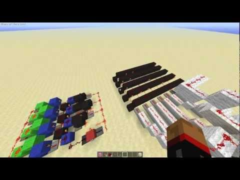
Video: Combining a Digital Display + RS NOR Latch Array [Advanced Minecraft Redstone Tutorials] by CNBMinecraft
How to build it
- Align the Array and Decoder
Ensure you have your seven-segment display with its decoder and your RS NOR latch array built with a 4-block gap between them. Each output line of the RS NOR latch array must line up directly with a corresponding number line on the decoder.
- Dig the Pre-Decoder Trenches
In the 4-block gap directly in front of each decoder input line, dig a 1-block-deep, 2-block-long trench.
- Place Trench Repeaters and Dust
Place a redstone repeater at the front of each 2-block trench facing toward the decoder, and place a piece of redstone dust in the trench space behind each repeater. Connect the output of these repeaters directly into the corresponding decoder lines.
- Add Pre-Decoder Blocks and Torches
Place a solid block directly above the redstone dust in each trench. Attach a redstone torch to the side of each of these blocks facing into the trench, and place a piece of redstone dust on top of each block.
- Chain the Pre-Decoder Lines
Place a redstone repeater between each of the solid blocks you just placed, facing into the adjacent block along the row. This allows an active line to power the block next to it and turn off the previous digit's torch.
- Bridge from the Latch Array
From the top of each output torch on your RS NOR latch array, build a line of solid blocks extending forward toward the pre-decoder. Step the final block down by one level just before it meets the redstone dust on top of the pre-decoder blocks.
- Wire the Bridge Lines
Place a redstone torch on the front face of the stepped-down block at the end of each bridge line so it powers the pre-decoder block ahead of it. Run redstone dust along the top of the bridge blocks all the way back to the RS NOR latch array torches.
- Cap the Final Digit Line
At the very end of the pre-decoder (on your highest digit line, such as 4 or 9), place a block and a permanent redstone torch feeding into the final repeater so that the last block in the pre-decoder chain receives constant power from that side.
How it works
An RS NOR latch counter works by sequentially flipping latches on in a row. When the counter is at 3, the latches for 0, 1, and 2 are all simultaneously in the 'on' state. If wired straight into a 7-segment decoder, the display would try to show 0, 1, and 2 at the same time.
- Signal Extraction: The bridge lines carry the output from the top of each RS NOR latch torch over to the pre-decoder, inverting the signal via a redstone torch at the end of each bridge.
- Signal Isolation (Pre-Decoder): Each line in the pre-decoder has a repeater feeding sideways into the neighboring line's block. When a higher number latch turns on, it powers its own decoder line while also sending power through the sideways repeater into the previous line's block.
- Torch Shutoff: Powering the previous line's block turns off its trench torch, cutting off the signal to the lower digit in the decoder. This ensures only the highest active latch in the array actually sends a signal through the trench repeater into the 7-segment decoder.
Tips & variations
- Scaling from 0–4 to 0–9: The demonstration uses a 5-line setup (digits 0 to 4), but you can easily expand it to a full 10-line display (0 to 9) by repeating the exact same tileable pattern for all ten lines and placing the permanent power torch cap at the end of the 9th digit line.
- Input Triggers: You can hook the add and subtract input lines of the RS NOR latch array up to buttons for a manual scoreboard, or connect them to pressure plates and detector rails to automatically count players or minecarts.
- Avoid Fast Clocks: This specific RS NOR latch array setup is best suited for manual or event-based counting (like minecart counters). Feeding a rapid automatic clock circuit into it is not recommended as the array timings can get messy.


