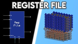
Video: Making A Register File - LRCWV Episode 3 by Professorvatcraft
How to build it
- Build a Single Locked-Repeater Latch
Place a redstone repeater leading into an output redstone lamp, with an input line feeding the back of the repeater. Run a second repeater directly into the side of the first repeater to act as the lock (clock) line; when powered, it locks the main repeater's current state (1 or 0).
- Stack Latches into an 8-Bit Register
Stack the single latch vertically until you have 8 layers on top of each other to represent an 8-bit binary number. Build a vertical glass tower with redstone dust alongside the side-locking repeaters so a single clock signal at the bottom locks or unlocks all 8 bits at once.
- Invert the Clock Line
At the base of the glass clock tower, place a solid block with a redstone torch powering the vertical dust line so the repeaters stay locked by default. Place a button on the block holding the torch; pressing it briefly turns off the torch, unlocking the repeaters to save new data.
- Duplicate to Create Four Registers
Build or copy three more identical 8-bit register towers in a row next to your first one, leaving enough space between them for wiring. You now have four separate 8-bit registers that make up the core of your register file.
- Connect the Shared Data Input Bus
Run 8 horizontal redstone dust lines across the back of all four registers, connecting the corresponding bit inputs of each tower together. Add repeaters along these bus lines to maintain signal strength, and place 8 input levers at the start of the bus to enter binary data.
- Wire the Write Clock & 2-Bit Decoder
Connect the clock inputs at the base of all four registers to a single write button, placing repeaters in front of each register's clock tower. Build a 2-to-4 decoder using two address levers and alternating redstone torches and repeaters so that each 2-bit combination (00, 01, 10, 11) unlocks only one register's clock line while keeping the other three blocked.
- Build the First Read Output Bus and Decoder
On the output side of the registers, merge the 8 bit levels from all four towers into a single 8-line read bus leading to a column of 8 redstone lamps. Build another 2-to-4 decoder below the output lines to lock or block the outputs of the unselected registers, allowing only the chosen register's data to reach the lamps.
- Mirror the Read Bus for Dual-Read Capability
Duplicate the entire read bus, 8-lamp display, and 2-bit read decoder onto the second output side of the registers. This creates a second independent read port, allowing you to read two different registers simultaneously using two separate 2-bit addresses.
- Add the Master Enable Circuit
Place redstone comparators set to subtract mode in line with your main control and input lines. Wire a master enable lever to feed maximum signal strength into the sides of these comparators when turned off, completely blocking signals from entering or leaving the register file until the lever is flipped on.
How it works
This circuit organizes memory hierarchically: latches make up registers, and registers make up the register file.
- Data Storage (D-Latch): Each bit is stored using Minecraft's repeater locking mechanic. A repeater constantly powered from the side by another repeater freezes its output state. Even if the shared 8-bit input bus changes, the locked repeaters ignore it.
- Writing Data: To write a number, you set the 8 input levers and choose a target register using the 2-bit write decoder. The decoder keeps three registers locked and primes the selected one. Pressing the clock button sends a pulse that briefly turns off the locking torch on the selected tower, allowing the new 8-bit value to pass into the repeaters before locking them again.
- Dual Reading: All four registers constantly output their stored values, which are gated before merging into the purple output buses. The two independent 2-to-4 read decoders let you unlock the output gates of up to two registers at once, sending their stored 8-bit binary values to Output A and Output B.
- Enable Line: The master enable circuit uses
subtract modecomparators. When disabled, a signal strength of 15 is subtracted from the inputs, reducing all signals to 0 and freezing the unit.
Tips & variations
- Color-Code Your Buses: Use different wool or concrete colors for the data input bus, the write decoder (cyan), the read buses (purple), and the enable line (brown) to make debugging much easier.
- WorldEdit for Stacking: If building in Creative mode on Java Edition, build one latch and use
//stack 7 upto instantly create an 8-bit register, then copy and paste the towers. - Glass Tower Direction: Remember that redstone signals only travel up transparent glass staircases, not down. Make sure your clock and decoder towers feed from the bottom up.
- ALU Integration: Connect the two dual-read output buses directly to inputs A and B of an Arithmetic Logic Unit (ALU), and loop the ALU's output back into this register file's data input bus to create a functional CPU datapath.