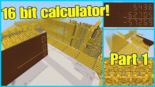
Video: HOW TO BUILD A REDSTONE CALCULATOR | A tutorial by Technical Minecraft! by Technical Minecraft
How to build it
- Set Up the Binary Inputs
Create two sets of input levers for your 4-bit binary numbers (A and B). Group them by place value (1, 2, 4, and 8) and lay out colored building blocks to serve as your signal buses.
- Build the First XOR Gate
For the ones place (inputs A1 and B1), construct an XOR gate. Place blocks in an X-shape with two extra blocks extending from the back, then add 5 redstone torches and 3 pieces of redstone dust to complete the exclusive-OR logic.
- Construct the Toggleable Inverter
Branch off input line A1 before it reaches the XOR gate to build a toggleable NOT gate. Place a raised block with a redstone torch on the side and redstone dust on top, then position a sticky piston behind it so pushing a block toggles between direct signal and inverted signal.
- Add the AND Gate for the Half Adder
Three blocks away from the XOR gate, build a standard 3-torch AND gate. Connect the output of the toggleable inverter into one side of the AND gate, and branch input line B1 directly into the other side.
- Wire the Half Adder Outputs
Run the output of the first XOR gate to a redstone lamp to display the ones-place digit (1). The output of the AND gate becomes your first Carry Out bit, which will feed into the next place value.
- Bus the Carry Bit to the Full Adder
Extend the Carry Out line from the half adder by 6 blocks towards the twos-place circuit. Place a solid block, a redstone repeater, and another solid block to boost the signal strength back to 15, then extend the line 3 more blocks and turn it downward.
- Build the Full Adder's First XOR Gate
Leave a 1-block gap from your carry bus and build a new XOR gate for the twos-place inputs (A2 and B2). Connect both input levers directly into the back of this XOR gate.
- Complete the First Half-Adder Stage
Extend the output of the A2/B2 XOR gate forward by 10 blocks into a second XOR gate. Branch off the input lines to build another toggleable sticky-piston inverter and an AND gate, completing the first half-adder section of your full adder.
- Connect the Carry Line to the Second Stage
Route the Carry Out bus from your very first half adder over the first AND gate using a raised block bridge and a repeater booster. Feed this line into the second input of the second XOR gate so it adds the carry bit to the A2/B2 sum.
- Add the Second AND Gate and Inverter
Branch off the carry input line and the first XOR output line to construct a second toggleable inverter and AND gate alongside the second XOR gate. This detects whether adding the carry bit generates a new carry.
- Merge Carry Outputs with an OR Gate
Connect the outputs of both AND gates in the full adder together into a single redstone line (an OR gate). If either AND gate activates, this combined line sends a Carry Out signal to the next bit's full adder.
- Repeat for Remaining Bits
Duplicate the full adder layout for the fours place and the eights place, feeding each Carry Out OR-gate into the Carry In of the next stage. Link all sticky piston inverters to a master 'Subtract Mode' lever and connect each final XOR output to your binary display lamps.
How it works
This calculator operates on 4-bit binary, where each bit represents a power of two (1, 2, 4, and 8). Instead of decimal digits, numbers are represented as ON (1) or OFF (0) signals.
- XOR Gates (Sum): An exclusive-OR gate outputs
1only when one input is ON, and turns OFF when both inputs are ON. This handles basic binary addition for a single column (1 + 0 = 1, while1 + 1 = 0with a carry). - AND Gates (Carry): Because
1 + 1equals2(written as10in binary), an AND gate checks if both inputs are ON simultaneously. When both are active, it sends a carry bit to the next place value. - Half Adder vs. Full Adder: The ones place uses a half adder (one XOR gate and one AND gate) because there is no previous column to carry from. Subsequent place values use a full adder, which chains two half adders and an OR gate together to sum Input A, Input B, and the incoming Carry bit.
- Toggleable Inverter (Subtraction): By placing a sticky piston next to a torch inverter on the A input lines before the AND gates, the circuit can invert the A signal when toggled. This converts the half adders and full adders into half subtractors and full subtractors, calculating
A - Bwhen the subtraction lever is pulled. - Signal Busing: Because redstone dust loses power after 15 blocks, running a wire into a solid block, a repeater, and another solid block extends the signal by 17 blocks total without losing strength.
Tips & variations
- Color-Code Your Buses: Use colored wool or concrete (like blue for main data buses) to keep track of inputs, carry lines, and logic gates in large circuits.
- Avoid Negative Numbers: This basic unsigned calculator does not use signed integers. Subtracting a larger number from a smaller number (e.g.,
0 - 1) will cause underflow and display unexpected binary outputs. - Watch Your Repeater Placement: When busing signals over long distances, place a solid block both before and after your repeaters to maximize the distance between signal boosters.
- Expanding to 8-Bit: A 4-bit input can represent numbers up to 15 (16 total values including 0). You can expand the calculator to 8 bits (up to 255) by simply tiling four more full adders onto the end of the carry chain.